Οι καλύτερες τεχνικές ανάκτησης ψυκτικού ρευστού

Η ανάκτηση του ψυκτικού ρευστού επιτρέπει την διεξαγωγή εργασιών στο ψυκτικό κύκλωμα χωρίς να απελευθερωθεί ποσότητα ψυκτικού ρευστού στο περιβάλλον. Τα περισσότερα ψυκτικά ρευστά είναι ισχυρά αέρια του θερμοκηπίου και θα πρέπει να περιορίζεται στο ελάχιστο η απόρριψή τους στο περιβάλλον. Εξάλλου ο Ευρωπαϊκός κανονισμός F-gasεπιβάλει την ανάκτηση του ψυκτικού ρευστού όταν απαιτείται εργασίες επισκευής ή ο παροπλισμού ψυκτικού κυκλώματος.
Ασφάλεια
Για οποιαδήποτε εργασία εκτελούμε πάντα πρέπει να λαμβάνεται υπόψιν η ασφάλεια. Για το λόγο αυτό:
- Χρησιμοποιούμε πάντα τα μέσα ατομικής προστασίας, γυαλιά, γάντια και εξοπλισμό ασφαλείας πριν οποιαδήποτε εργασία
- Φροντίζουμε για τον όσο το δυνατό καλύτερο εξαερισμό του χώρου
Πάντα ζυγίζουμε και προσέχουμε το βάρος της φιάλης στην οποία κάνουμε ανάκτηση ώστε να μην ξεπεράσουμε το μέγιστο βάρος πλήρωσης - Η φιάλη στην οποία κάνουμε ανάκτηση θα πρέπει να είναι κατάλληλη για το ψυκτικό ρευστό το οποίου ανακτούμε και θα πρέπει να μην έχει ξεπεράσει την ημερομηνία λήξης της (οι φιάλες ανάκτησης θα πρέπει να ελέγχονται και να επαναπιστοποιούνται κάθε 5 χρόνια)
- Στρέφουμε την ασφαλιστική βαλβίδα της φιάλης μακριά από όσους δουλεύουν στο χώρο
- Δεν θα πρέπει να αναμειγνύονται διαφορετικά ψυκτικά ρευστά στην ίδια φιάλη ανάκτησης
- Στην φιάλη θα πρέπει να αναγράφεται το ψυκτικό ρευστό που ανακτήθηκε καθώς και η σημείωση ότι πρόκειται για ανακτημένο ψυκτικό ρευστό
- Η πίεση στη φιάλη δεν θα πρέπει να ξεπερνάει την επιτρεπόμενη από τη φιάλη πίεση
Μέγιστη ποσότητα πλήρωσης
Αν η φιάλη στην οποία θα γίνει η ανάκτηση αναγράφει το μέγιστο βάρος πλήρωσης για το ψυκτικό ρευστό που ανακτούμε θα πρέπει να χρησιμοποιείται αυτή η τιμή για τη μέγιστη ποσότητα πλήρωσης. Σε διαφορετική περίπτωση με βάση τον Ευρωπαϊκό κανονισμό ΕΝ378 θα πρέπει να υπολογιστεί η μέγιστη ποσότητα πλήρωσης. Το ψυκτικό ρευστό που ανακτάται είναι αναμεμιγμένο με μία ποσότητα λιπαντικού με αποτέλεσμα να έχει χαμηλότερη πυκνότητα σε σχέση με το καθαρό ψυκτικό ρευστό. Για το λόγο αυτό η ποσότητα πλήρωσης της φιάλης πρέπει να είναι μικρότερη σε σχέση με τη χωρητικότητά της σε καθαρό ψυκτικό ρευστό. Βάση του κανονισμού η μέγιστη ποσότητα πλήρωσης υπολογίζεται με 2 τρόπους και ισχύει η χαμηλότερη από τις δύο τιμές:
Τρόπος 1. 80% της μέγιστης ποσότητα πλήρωσης καθαρού ψυκτικού ρευστού της φιάλης
Τρόπος 2. 70% του όγκου της φιάλης
Για παράδειγμα σε μία φιάλη που αναγράφει ότι η ποσότητα καθαρού ψυκτικού ρευστού R134aπου μπορεί να περιέχει είναι 15 kgκαι ο όγκος της είναι 15,3 lt τότε:
Τρόπος 1. 0,8 x 15 = 12kg
Τρόπος 2. 0,7 x15,3 lt = 10,71 lt. Η πυκνότητα του R134aστους 25°C είναι 1,206kg/lt άρα η μέγιστη ποσότητα πλήρωσης είναι 10,71 x 1,206 = 12,92 kg
Όπως φαίνεται ο τρόπος 1 υπολογίζει μικρότερη ποσότητα άρα αυτή καθορίζει την μέγιστη ποσότητα πλήρωσης της φιάλης στην οποία πραγματοποιούμε την ανάκτηση.
Στην περίπτωση ανάκτησης υδρογονανθράκων δεν θα πρέπει να υπερβαίνεται το 45% της μέγιστης πλήρωσης.
Εξοπλισμός
Ο απαραίτητος εξοπλισμός για την ολοκλήρωση της εργασίας ανάκτησης ψυκτικού ρευστού αποτελείται από:
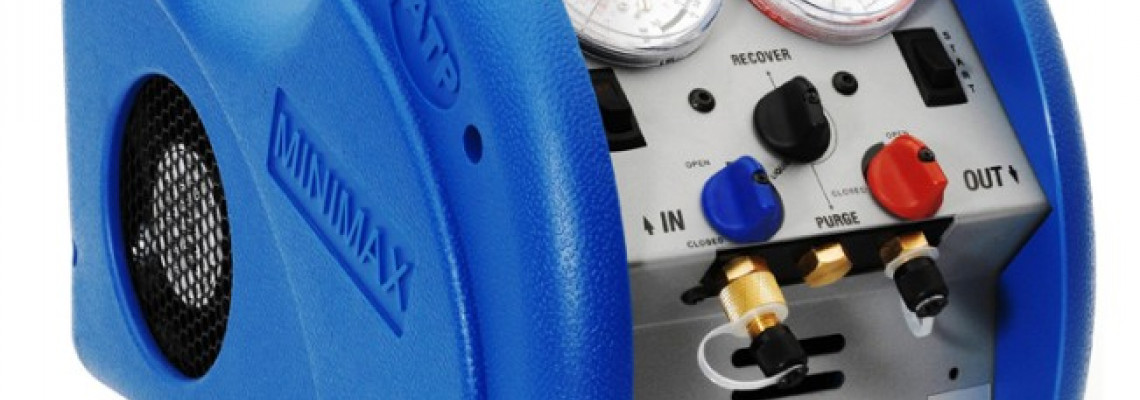
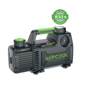
- Μηχανή ανάκτησης κατάλληλη για το ψυκτικό ρευστό που θα ανακτήθεί (Εικόνα 1)
- Ζυγαριά
- Ελαστικοί σωλήνες και εξαρτήματα σύνδεσης
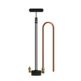
- Εργαλείο αφαίρεσης του πυρήνα των ελαστικών σωλήνων
- Φίλτρο
- Φιάλη ανάκτησης
- Μέσα Ατομικής Προστασίας

Εικόνα 1. Μηχανή ανάκτησης
Τεχνικές ανάκτησης ψυκτικών ρευστών
Ο συνηθέστερος τρόπος ανάκτησης είναι η χρήση μιας μηχανής ανάκτησης η οποία αφαιρεί υγρό και αέριο ψυκτικό ρευστό από το σύστημα και το μεταφέρει σε μία φιάλη. Ωστόσο υπάρχει διάφοροι τρόποι σύνδεσης που μπορούν να αυξήσουν τη ροή ανάκτησης (μειώνοντας τον χρόνο) και να αποτρέψουν την αύξηση της πίεσης στη φιάλη.
Η πιο συνηθισμένη τεχνική (εικόνα 3) είναι η σύνδεση των μανομέτρων με το κύκλωμα και τη μηχανή ανάκτησης με ελαστικούς σωλήνες ¼ in. και στη συνέχεια σύνδεση της μηχανής ανάκτησης με τη φιάλη πάλι με ελαστικούς σωλήνες ¼ in. Στην είσοδο της μηχανής ανάκτησης θα πρέπει πάντα να τοποθετείται φίλτρο για την προστασία της. Με αυτή τη σύνδεση μπορούμε να ανακτήσουμε τόσο υγρό όσο και αέριο ψυκτικό ρευστό από το κύκλωμα.

Εικόνα 2. Εργαλείο αφαίρεσης πυρήνων από βαλβιδάκια.
Για να επιτύχουμε γρηγορότερη ανάκτηση θα πρέπει:
- Να αφαιρούνται οι πυρήνες από τα βαλβιδάκια του συστήματος στα οποία συνδέουμε τους ελαστικούς σωλήνες για την ανάκτηση (Εικόνα 2). Οι πυρήνες αυτοί μπλοκάρουν περίπου το 95% της ροής από το βαλβιδάκι.
- Να αφαιρούνται τα εξαρτήματα των ελαστικών σωλήνων που σπρώχνουν το βαλβιδάκι καθώς μπλοκάρουν περίπου το 50% του ελαστικού σωλήνα.
- Ακόμα και αν οι βαλβίδες serviceτου κυκλώματος είναι ¼ in. θα πρέπει να χρησιμοποιούνται ελαστικοί σωλήνες 3/8in. τόσο στην σύνδεση με το κύκλωμα όσο και στη σύνδεση της μηχανής ανάκτησης με τη φιάλη. Η διατομή των ελαστικών σωλήνων έχει μεγάλη επίδραση στην ταχύτητα ανάκτησης.
- Οι ελαστικοί σωλήνες θα πρέπει να έχουν όσο το δυνατό μικρότερο μήκος ώστε να μην επιβραδύνεται η ροή αλλά και να μην παγιδεύεται μεγάλη ποσότητα ψυκτικού ρευστού σε αυτούς.
- Ο ελαστικός σωλήνας από τη μηχανή ανάκτησης στη φιάλη θα πρέπει να συνδέεται στη βάνα του αερίου της φιάλης. Με αυτό τον τρόπο το ψυκτικό ρευστό δεν χρειάζεται να περάσει από το λεπτό σωληνάκι που έχει η φιάλη στη βάνα του υγρού και θα περιόριζε τη ροή.
- Εφόσον χρησιμοποιείται μικρή φιάλη, η φιάλη θα πρέπει να είναι γυρισμένη ανάποδα όσο ανακτάται υγρό ψυκτικό ρευστό και να τοποθετείται στην κανονική της θέση όταν έχει ανακτηθεί όλη η ποσότητα του υγρού ψυκτικού ρευστού και πλέον ανακτάται αέριο. Αυτό περιορίζει όσο το δυνατόν την αύξηση της πίεσης της φιάλης. Καθώς ο ρυθμός ανάκτηση είναι πολύ υψηλότερος όσο ανακτάται υγρό ψυκτικό ρευστό, παρακολουθώντας τη ζυγαριά είναι εύκολο να καταλάβουμε πότε η μηχανή ανάκτησης ξεκινά να ανακτά αέριο ψυκτικό ρευστό.

Εικόνα 3. Συνήθης σύνδεση ελαστικών σωλήνων για ανάκτηση ψυκτικού ρευστού.
Κατά τη διάρκεια της ανάκτησης η θερμοκρασία της φιάλης ανάκτησης ανεβαίνει. Ο λόγος που ανεβαίνει η θερμοκρασία στη φιάλη είναι η είσοδος αέριου ψυκτικού ρευστού σε αυτή. Για την συμπύκνωση του αέριου ψυκτικού ρευστού η φιάλη πρέπει να αποβάλλει θερμότητα στο περιβάλλον με αποτέλεσμα να ανεβαίνει η θερμοκρασία της φιάλης. Υπάρχουν δύο τρόποι να περιορίσουμε την αύξηση της θερμοκρασίας της φιάλης.
- Παρεμβάλουμε μεταξύ της μηχανής ανάκτησης και της φιάλης ανάκτησης ένα σύστημα μηχανικής υπόψυξης. Ουσιαστικά προσθέτουμε ένα condensingunit το οποίο ψύχει το ψυκτικό ρευστό προτού φτάσει στη φιάλη, εξασφαλίζοντας ότι θα πηγαίνει στη φιάλη σε υγρή κατάσταση. Ωστόσο κάτι τέτοιο αυξάνει την πολυπλοκότητα και επιπλέον αυξάνει τα μέτρα ελαστικών σωλήνων που χρησιμοποιούνται άρα παγιδεύεται μεγαλύτερη ποσότητα ψυκτικού ρευστού.
- Κρυώνουμε τη φιάλη με νερό, πάγο η βρεγμένα πανιά. Με αυτό τον τρόπο βοηθάμε τη φιάλη να αποβάλλει την θερμότητα συμπύκνωσης του αέριου ψυκτικού ρευστού.
Ένας άλλος τρόπος να ελαττωθεί ο χρόνος ανάκτησης είναι η διαφορετική σύνδεση των ελαστικών σωλήνων. Τροποποιώντας λίγο την προηγούμενη σύνδεση (εικόνα 4), προσθέτουμε έναν ελαστικό σωλήνα από τη βάνα αερίου της φιάλης στη γραμμή αερίου του κυκλώματος. Η διαφορά πίεσης επιτρέπει στο αέριο ψυκτικού ρευστό της φιάλης να επιστρέφει στο κύκλωμα και στη συνέχεια να ανακτάται πάλι από τη μηχανή ανάκτησης, βοηθώντας στην ψύξη της φιάλης.

Εικόνα 4. Τεχνική σύνδεσης ελαστικών σωλήνων για ταχύτερη ανάκτηση ψυκτικού ρευστού.
Τέλος, ένας διαφορετικός τρόπος σύνδεσης είναι η μέθοδος push-pull (εικόνα 5). Σε αυτή τη μέθοδο η μηχανή ανάκτησης παίρνει αέριο ψυκτικό ρευστό από τη φιάλη και το εισάγει στο κύκλωμα συμπιεσμένο ώστε να «σπρώξει» το υγρό ψυκτικό ρευστό απευθείας στη φιάλη. Όταν έχει ανακτηθεί ολόκληρη η ποσότητα του υγρού ψυκτικού ρευστού η ανάκτηση θα πρέπει να συνεχίζει με την προηγούμενη συνδεσμολογία. Η διαδικασία αυτή χρησιμοποιείται μόνο σε ψυκτικά κυκλώματα με μεγάλη ποσότητα ψυκτικού ρευστού.

Εικόνα 5. Σύνδεση ελαστικών σωλήνων για ανάκτηση ψυκτικού ρευστού με τη μέθοδο Push-Pull.
Περίληψη
Η ανάκτηση του ψυκτικού ρευστού είναι μία χρονοβόρα διαδικασία η οποία είναι όμως απαραίτητη και δεν πρέπει σε καμία περίπτωση να αντικαθίσταται από την απόρριψη του ψυκτικού ρευστού στο περιβάλλον. Υπάρχουν όμως αρκετές τεχνικές οι οποίες μπορούν να μειώσουν σημαντικά το χρόνο ανάκτησης ανάλογα με την εκάστοτε εφαρμογή. Η ανάκτηση πρέπει να γίνεται από εξειδικευμένο προσωπικό με άδεια ψυκτικού και πιστοποίηση διαχείρισης ψυκτικών ρευστών με βάση τον Ευρωπαϊκό κανονισμό F-gas.
Βιβλιογραφία
[1] Ευρωπαϊκός κανονισμός ΕΝ378
[2] AshraeHandbook – Refrigeration
[3] Promaxminimaxmanual
%20(1)-1000x500.png)


-275x275.jpg)




-275x275.jpg)
-275x275.png)
-275x275.jpg)
-275x275.jpg)


-275x275.jpg)

-275x275.jpg)
-275x275h.jpg)
-275x275h.jpg)
-275x275h.jpg)


-275x275.jpg)
-275x275.jpg)


-275x275.jpg)
-275x275.jpg)


Σχολιάστε